27 PHOTOGRAMMETRY
Asterisks
(*)
indicate problems that have partial answers given in Appendix G.
27.1 Describe the difference between vertical, low oblique, and high oblique aerial
photos.
27.2 Define the term interpretative photogrammetry.
27.3 Define the term metric photogrammetry.
(a) From Section 27.1, Paragraph 4: “Metrical photogrammetry is accomplished
in different ways depending upon project requirements and the type of equipment
available. Simple analyses and computations can be made by making
measurements on paper prints of aerial photos using engineer’s scales, and
assuming that the photos are “truly vertical,” that is, the camera axis coincided
27.4 Describe briefly an unmanned aerial system.
27.5 The distance between two points on a vertical photograph is ab and the
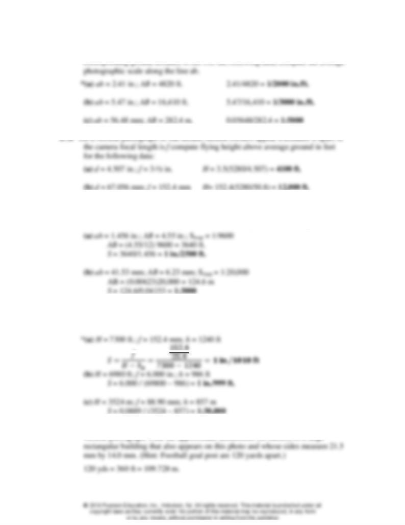
27.7 On a vertical photograph of flat terrain, the scaled distance between two points is
ab. Find the average photographic scale along ab if the measured length between
the same line is AB on a map plotted at a scale of Smap for the following data.
27.8 What are the average scales of vertical photographs for the following data, given
flying height above sea level, H, camera focal length, f, and average ground
elevation h?
27.9 The length of a football field from goal post to goal post scales 49.15 mm on a
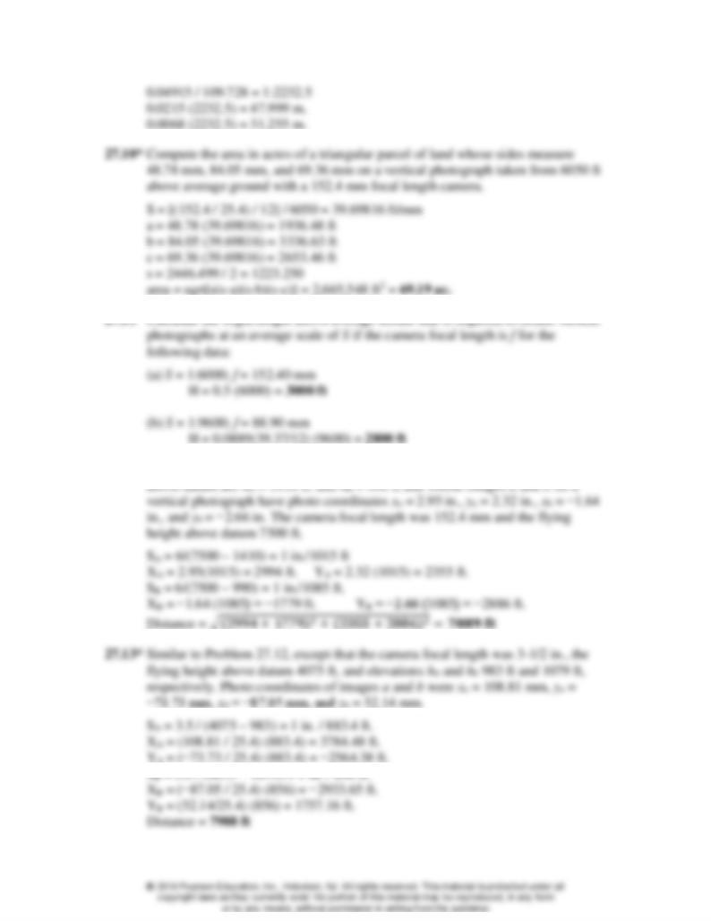
27.12 Determine the horizontal distance between two points A and B whose elevations
YD = 3.09 (1055) = 3261 ft.
27.17 On a vertical photograph, images a and b of ground points A and B have
2
fyhHyhH
fxhHxhH
Laabbaabb
22
yb = −59.29 mm line length AB = 4695 ft. and elevations of points A and B are
925 and 875 ft, respectively.
a
a
b
27.23 List the four different categories of stereoscopic plotting instruments.
27.24 Name the three stages in stereoplotter orientation, and briefly explain the
objectives of each.
From Section 27.14, Paragraphs 5 – 7: “A stereoplotter operator, preparing to
measure or map a stereomodel, must go through a three-stage orientation process
consisting of interior orientation, relative orientation, and absolute orientation.”
Interior orientation ensures that the projected light rays are geometrically correct,
i.e., angles 𝜃1
′ and 𝜃2
′ of Figure 27.14(b), (i.e., the angles between the projected
light rays and the axis of the projector lens), must be identical to corresponding
angles 𝜃1 and 𝜃2 respectively, in Figure 27.14(a), (i.e., the angles between the
incoming light rays and the camera axis). Preparing the diapositives to exacting
specifications, and centering them carefully in the projectors accomplish this.
After the diapositives have been placed in the projectors and the lights turned on,
manuscript map prepared at the desired scale. It is leveled by adjusting the
27.25 How can the operator’s left and right eyes restricted to the left and right images,
respectively?
27.27 Compare an orthophoto with a conventional line and symbol map.
27.28 Discuss the advantages of orthophotos as compared to maps.
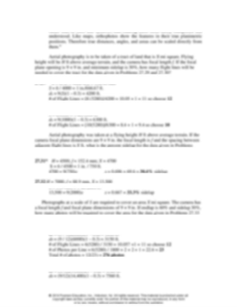
From Section 27.15, Paragraph 4: “Orthophotos combine the advantages of both
aerial photos and line maps. Like photos, they show features by their actual images
27.30 X = 10; H = 6000 ft; f = 6.000 in.
27.31 and 27.32?
and 27.34?
27.33 S = 1:6000; X = 6; f = 152.4 mm
27.34 S = 1:14,400; X = 40; f = 3.5 in.
# of Flight Lines = 40(5280) / 7560 = 27.9 +1 = 28
27.35 Describe a system that employs GNSS and that can reduce or eliminate ground
control surveys in photogrammetry?
27.36 To what wavelengths of electromagnetic energy is the human eye sensitive? What
wavelengths produce the colors blue, green, and red?
27.37 Discuss the uses and advantages of satellite imagery.
From Section 27.19: “Satellite imagery is unique because it affords a practical
means of monitoring our entire planet on a regular basis. Images of this type have
Problems 27.38 through 27.42 involve using WolfPack with images 5 and 6 on the
CD that accompany this book. The ground coordinates of the paneled points are listed in
the file “ground.crd.” The coordinates of the fiducials are listed in the file “camera.fid.” To